
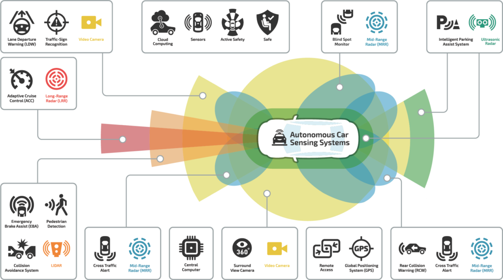
The widespread adoption of autonomous vehicles (AVs) is only possible if the electronic circuitry is reliable and robust to any electrical shocks. Today’s electronics engineers reduce the risk of critical circuit failures by providing the proper protection from overcurrents, electrostatic discharges (ESD), transient surges, and reverse polarity for three mission-critical AV subsystems—the camera, radar, and ADAS.
Protecting camera subsystems
Multiple cameras work together, providing situational awareness for the driver while converting available light through a CCD/CMOS image sensor into signals sent to the communication and control circuits (Figure 2).
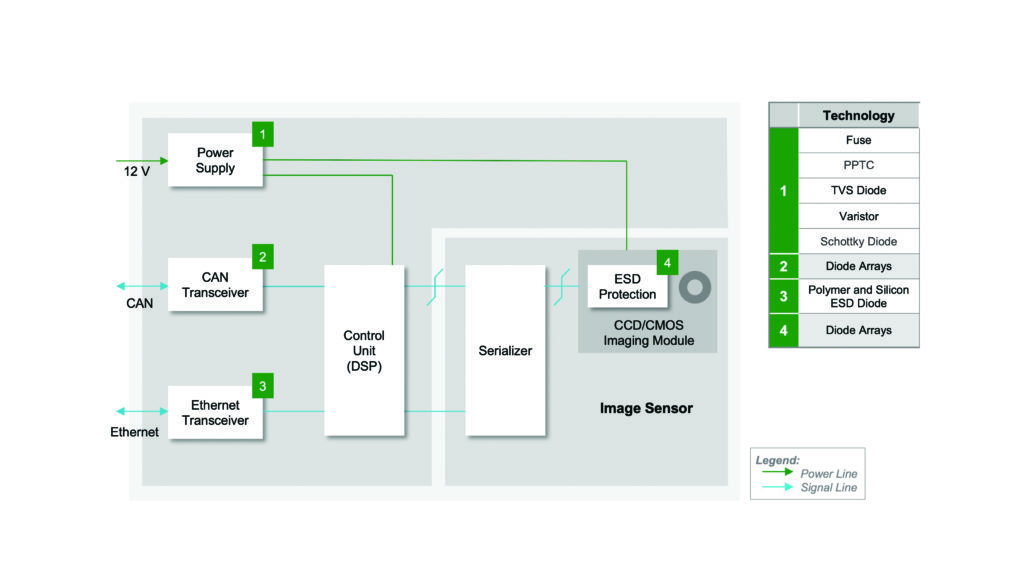
To protect the Camera Power-Supply Subsystem from overcurrent, high energy transients, and reverse polarity, select either a polymer-based positive temperature coefficient (PPTC) resettable fuse or a surface-mountable ceramic fuse with single-shot usage. The PPTC’s advantage is that it does not require replacement after an overcurrent condition. The PPTC exponentially increases in resistance in response to the heat generated by an overcurrent. Once the overcurrent is removed, the PPTC returns to low resistance, causing the circuit to reset.
Power supply circuits also require protection from any high-energy transients inside the vehicle (e.g., energizing motors) and should withstand transients defined by the ISO Standards 7637 and 16750. Transient voltage suppressor (TVS) diodes can safely absorb low- and high-energy transients specified in the referenced ISO standards.
If reversed voltage polarity to the power supply is possible, utilize a Schottky diode in series with the fuse to avoid failure. The diode’s low forward voltage drop has minimal impact on power supply performance while providing reverse polarity protection.
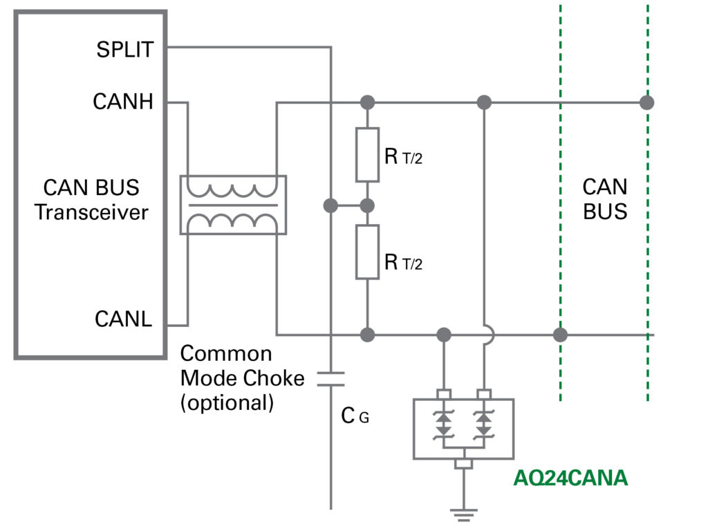
The Controller Area Network (CAN) Transceiver should have adequate protection from ESD. TVS diode arrays provide high ESD robustness with numerous options (discrete, two-channel arrays) having 30kV air and 30kV contact discharge capabilities. These devices help meet ISO Standard 10605 for ESD in vehicles. An efficient solution is to protect both the high and low lines with a two-channel TVS diode array, like the Littelfuse AQ24CANA (Figure 3).
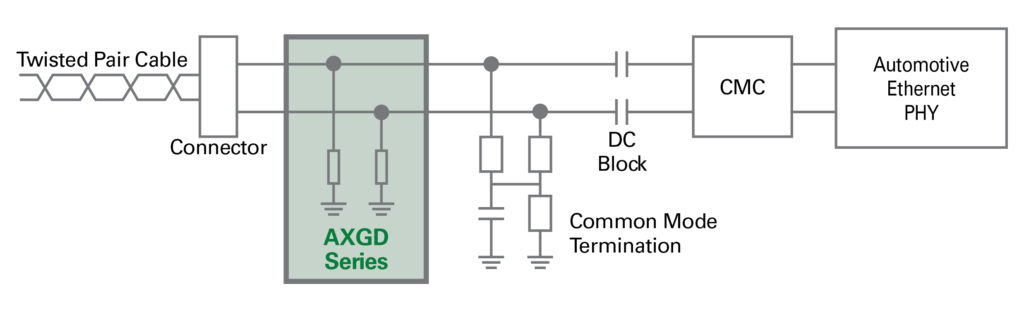
The Ethernet transceiver also needs ESD protection. Diode arrays and polymer ESD suppressors can provide the necessary protection for high-speed differential data lines. These diode arrays can provide up to ±30kV ESD protection and protect a differential line pair in a single package for PCB space savings. In systems where the capacitance must be the absolute lowest, consider polymer ESD suppressors with 0.04pF, such as the Littelfuse AXGD (Figure 4). Since the capacitance is this low, it will not impede 1 Gbit Ethernet transmission rates.
Protect the Image Sensor and CCD/CMOS Imaging Module with a bidirectional, low-capacitance protection component (Figure 5). This TVS diode array can withstand ESD strikes of up to ±30kV, has a capacitance of around 0.35pF, and extremely low leakage current (typically < 10nA). Available in an ultra-small SOD882 package, it provides exceptional space efficiency.
Using the recommended components as close to the four camera subsystem’s inputs as possible will keep extraneous energy from damaging critical circuits, ensuring a reliable visible-light detection system.
Protecting radar subsystems
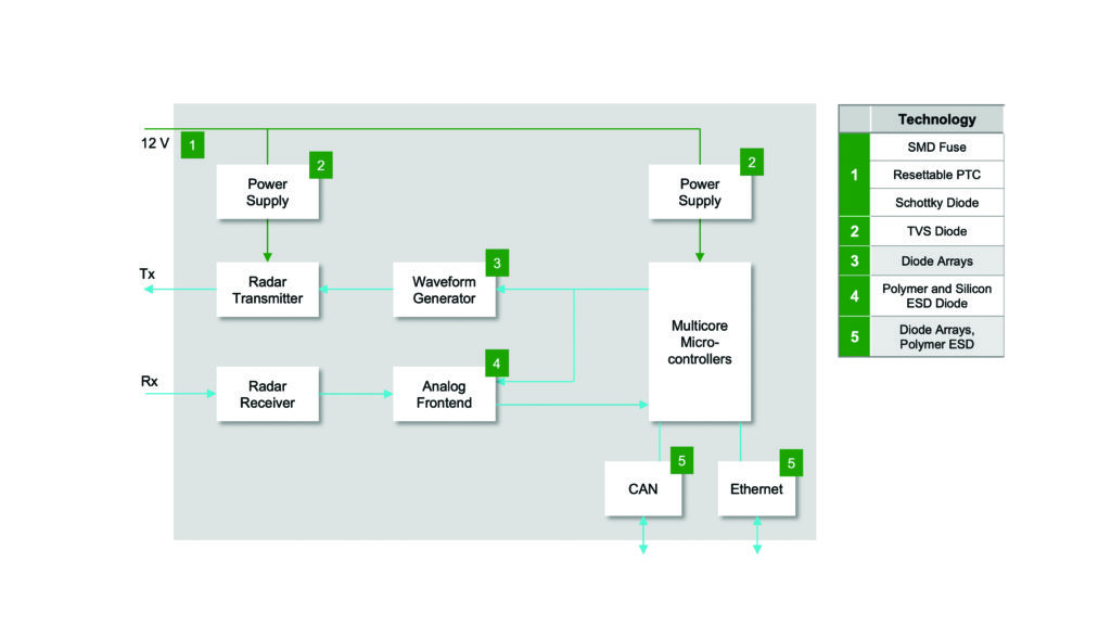
The radar subsystem provides inputs for the critical forward and side pedestrian detection and collision avoidance functions (Figure 6). The circuit uses two DC power supplies. The power supply that powers the analog radar transmitter is a low-noise supply, and a conventional power supply powers the logic/communication circuits.
The Radar Subsystem Power Supplies, similar to the camera subsystem power supply, require overcurrent, transient surge, ESD, and reverse polarity protection.
One set of circuit protection devices can protect both supplies from overcurrent and reverse polarity. Use either a surface-mounted fuse or a resettable PPTC. Provide reverse polarity protection for the power supplies and all the radar subsystem circuits by utilizing a low forward voltage Schottky diode in series with the input line to both supplies. Remember to provide each power supply with surge protection at the input.
To adequately protect the power supplies from surges, be sure to choose a TVS diode based on its transient power rating (400-600W for low power transients and 1,500-7,000W for high power transients).
The Waveform Generator and Analog Frontend are part of the radar transmitter and receiver, respectively. They are separated from the transmitter and receiver circuits since adding protection components on the transmitter output, and receiver input blocks could alter their transmission and reception impedance.
For the camera subsystem’s image sensor, use a bidirectional clamping component, like an ESD diode.
The radar subsystem transmits its information to the vehicle’s central processing subsystem. Use bidirectional diode arrays to provide ESD protection for both the CAN bus I/O lines. Also, use either diode arrays or polymer ESD suppressors for the Ethernet transceiver to minimize signal distortion and not impact the transmission rate.
Protecting ADAS communication/control subsystems
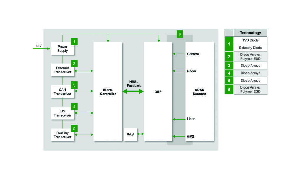
The control, communications, and signal processing subsystem must identify other vehicles in traffic, make fast stops due to an obstruction in the vehicle’s path, and must have to have a fail-safe response when a sensor fails. While never-fail firmware is critical, the circuit designer should focus on ensuring that the hardware survives any transient energy strikes. All circuits that supply information to the ADAS control subsystem need robust ESD protection (Figure 7).
The ADAS subsystem requires protection from overcurrent, surges, and reverse polarity. Design the power supply fuse within the module or further upstream in the vehicle’s low-voltage junction box. Select a TVS diode by its surge power rating to provide the best possible surge transient protection. A Schottky diode in series with the power supply input provides reverse voltage polarity protection.
Use ESD protection for each communication link —design to fit each port’s unique requirements (Table 1). Select from TVS diode arrays and polymer ESD suppressors with unique characteristics to protect each port without compromising the data rate or high-to-low voltage differential.
| Protocol | Bit Rate / Frequency |
| LIN | < 20 kbps |
| CAN | < 1 Mbps to < 10 Mbps |
| Automotive Ethernet | 100 Mbps, 1 Gbps |
Table 1. Automotive communication protocols
Signal lines connecting directly to the DSP circuits require ESD protection. Electronics engineers can use TVS diode arrays or polymer ESD suppressors that provide bidirectional protection for the high and low signal lines.
Ensuring that the ADAS subsystem remains operational is mission-critical. Incorporate ESD protection on all subsystem inputs/outputs, using TVS diodes for surge protection against transients generated by electric and electromechanical devices, installing Schottky diodes for reverse polarity protection, and fuses or PPTCs for overcurrent conditions.
Conclusion
A diverse selection of components is available to protect today’s advanced automotive circuitry from electrical stresses. Be sure to use AEC-Q-qualified components to help accelerate compliance with quality and reliability standard requirements. Doing so will give the design team and manufacturer confidence that the board-level components will provide robust circuit protection to ensure highly reliable performance and long life.
For more information, see the Automotive Electronics Applications Guide, courtesy of Littelfuse.
This article was provided by Littelfuse


